In this post, I will present to you how to implement a final state machine(FSM) that describes the functionality of a vending machine:
Problem:
Suppose we have a vending machine that sells soda cans that costs a 2$ each.
Moreover we have only 3 types of coins: 1$, 2$ and 5$.
Our objective is to design a state machine that determines when to dispense a can, how to return the change.
Note: in this design we will ignore the capacity of the stock, which means, we’ll assume that there will always be can in the vending machine.
Also, we can assume that only one action could be made in every “clock cycle” or state
RULES:
first give back the change then dispense the can
Understanding the possibilities :
there are quite few options:
1) entering no money
2)putting 1$ followed by another 1$ => getting the can
3)putting 1$ followed by 2$ => receiving change => getting a can
4)putting 1$ followed by 5$ => receiving change => getting a can
5)putting 2$ and getting the can
6)putting 5$ => receiving change => getting a can.
Above, is the “big picture” of the options or states of the machine, note that if you put a sum of money which is more or equal to 2$, you cant put more money(since it would be meaningless, no?!)
FSM diagrame:
Basically, what we’ll do now is translating the options we stated above into a flow chart/FSM diagram:
*Note: 0$ = “00”, 1$ = “01”, 2$=”10″, 5$ = “11”
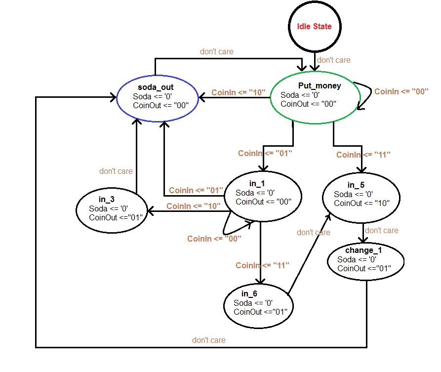
Note that the FSM is a Moore machine, since the output relates to the current state.
explaining the states :
1)put_money: this is the first state after ‘idle’, here the customer puts in the coins.
2)in_5: If the customer put 5$, the machine moves to this state. Pay attention that the machine gives back a 2$ change without dispensing the can yet.
3)change_1: after giving a 2$ change for the customer who paid 5$we need to give back another 1$ change. Here, in this state we do exactly that. again, note that the can still has not been dispensed yet!
4)in_1, in_3, in_6: we get to those states depending on the sum of money that been inserted by the customer.
5)soda_out: dispensing out the soda can!
VHDL code:
library ieee;
use IEEE.std_logic_1164.all;

entity FSM is
port (CLK : in std_logic; --Clock, active high
 RSTn : in std_logic; --Async. Reset, active low
 CoinIn : in std_logic_vector (1 downto 0); --Which coin was inserted
 Soda : out std_logic; --Is Soda dispensed ?
 CoinOut : out std_logic_vector (1 downto 0) --Which coin is dispensed?
 );

end entity;

architecture behavior of FSM is
-- add your code here
type state_type is (idle, --start state/reset
 put_money, --waiting to enter money
 in_1,in_3,in_6,in_5, --represent the current sum of money after returning change
 change_1, --should return change of 1$
 soda_out --dispence soda can.
 ); --type of state machine.
signal current_s,next_s: state_type; --current and next state declaration.

begin

process(CLK,RSTn)
begin
 if(RSTn = '0') then
 current_s <= idle; --defualt state is on RESET
 elsif(clk'event and clk = '1') then
 current_s <= next_s;
 end if;
end process;
--------------------
--FSM process:
process(current_s,CoinIn)
begin
case current_s is
 when idle => --state reset or idle
 Soda <= '0';
 CoinOut <= "00";
 next_s <= put_money;
 ------------------------------------------------------
 when put_money => --wait for money to be entered
 if(CoinIn = "00")then
 Soda <= '0';
 CoinOut <= "00";
 next_s <= put_money;
 elsif(CoinIn = "01")then --insert 1$
 Soda <= '0';
 CoinOut <= "00";
 next_s <= in_1;
 elsif(CoinIn = "10")then --insert 2$
 Soda <= '0';
 CoinOut <= "00";
 next_s <= soda_out;
 elsif(CoinIn = "11")then --insert 5$
 Soda <= '0';
 CoinOut <= "00";
 next_s <= in_5;
 end if;
 ------------------------------------------------------
 when in_1 =>
 if(CoinIn = "00") then--stay on the same state
 Soda <= '0';
 CoinOut <= "00";
 next_s <= in_1;
 elsif(CoinIn = "01") then--inserted another 1$
 Soda <= '0';
 CoinOut <= "00";
 next_s <= soda_out;
 elsif(CoinIn = "10") then--inserted another 2$
 Soda <= '0';
 CoinOut <= "00";
 next_s <= in_3;
 elsif(CoinIn = "11") then
 Soda <= '0';
 CoinOut <= "10";
 next_s <= in_6;
 end if;
 ------------------------------------------------------
 when in_3 =>
 Soda <= '0';
 CoinOut <= "01";
 next_s <= soda_out;
 ------------------------------------------------------
 when in_6 =>
 Soda <= '0';
 CoinOut <= "01";
 next_s <= in_5;
 ------------------------------------------------------
 when in_5 => -- input = 5 coin
 Soda <= '0';
 CoinOut <= "10";
 next_s <= change_1;
 ------------------------------------------------------
 when change_1 => -- input = 5 coin
 Soda <= '0';
 CoinOut <= "01";
 next_s <= soda_out;
 ------------------------------------------------------
 when soda_out =>
 Soda <= '1';
 CoinOut <= "00";
 next_s <= put_money;
end case;
end process;

end behavior;


Great article.do u please have the transition tables and circuit for this moore fsm?
would please like to use it for academic purpose.thanks
LikeLike
I didn’t build any tables back then, only the vhdl code. You can use it for academic purposes for sure as you like. Thanks for tuning in 🙂
LikeLike
Assuminig i want to display it on fpga do i need to implement the test bench or i can just creat a vector to call the values
LikeLike
I believe that a testbench is more elegant and neat – easy to test every possible scenario out there.
LikeLike
Hey ThunderWiring I have something similar I need help with. Are you able to help
LikeLike
Hi Ashley,
Of course, what do you have? please send it and we can figure something together!
LikeLike
awesome!!!!!!!!!!!!!!!! where do I send it?
LikeLike
The objective of this project is to implement, in VHDL, a Finite State Machine, using the main clock of the Digilent Board to drive the state machine. The finite state machine will control a vending machine to dispense soda cans that are worth 50¢. Since this project will require several modules, consider using a mixed schematic/VHDL design, where you can use a schematic as the top level module, and have each sub-module defined in VHDL.
The vending machine has three inputs:
QUARTER: a signal that goes high and then low when a quarter has been deposited
CLOCK: a clock that will drive the FSM
RESET: a signal that will reset the FSM to its initial state
The vending machine has two outputs:
COUNT: a signal that goes high when a single quarter has been accepted. This signal should remain high for one clock cycle.
DISPENSE: a signal that goes high when the soda has been dispensed
Part I
Create a clock divider module to divide the master clock (at 50MHz) to a 1Hz clock. You may also need to create a switch debouncer for the QUARTER input to avoid confusing the FSM.
Part 2
Create your state diagram that you will use to implement the FSM VHDL module. The vending machine behaves as follows:
• If the RESET input is asserted, the FSM will go to the initialization state (S_init) immediately. All of the outputs should be zero in this state.
• From the initialization state S_init, the FSM will unconditionally go to the wait state (S_wait)
• From the wait state S_wait, the FSM waits for the QUARTER switch to be activated.
• If QUARTER is asserted, the FSM goes to state S_Q1. In this state, the COUNT output is set to 1, indicating that a quarter has been accepted. The FSM will stay in this state until the QUARTER input is de-asserted. When this occurs, the FSM goes to state S_QW1, then unconditionally to state S_QW2 and the COUNT output is set to 0. The FSM waits for the QUARTER switch to be activated.
• If QUARTER is asserted while the FSM is in S_QW2, then the state machine goes to state S_Q2. In this state, the COUNT output is again set to 1. The FSM will stay in this state until the QUARTER input is de-asserted. When this occurs, the FSM goes to S_QW3, and then unconditionally to state S_dispense, the COUNT output is set to 0, and the DISPENSE output is set to 1.
• From state S_dispense, the FSM unconditionally goes to state S_init.
Your VHDL MUST have two process: a next-state process to determine the change of states, and a output_logic process, to determine the outputs. Please include a state diagram and test bench outputs
LikeLike
Have you understood what happened in the article? because it is very (very) similar what they are requiring from you to do in your HW.
This is a very classic question on FSM with VHDL.
if you have a *specific* question about concept/implementation, i can happily help,
LikeLike
To be honest with your our professor didn’t explain much in digital and we are struggling that’s why I’m asking for help 😦
LikeLike
i know, me too, back when i got this assignment it wasn’t the clearest thing, that’s among the reasons i made this post.
The most important thing, i suggest you start with is understanding the states of the FSM that you need.
Then, you should draw them to understand the relation (no VHDL until now).
After you are fully certain about your design, try to look at the code i posted, if there are somethings which are not clear, ask me about them.
So to sum it up, do the design (on paper) for your FSM.
LikeLike
I’m trying to do the design but I’m looking at your diagram and now I got stuck when I looked at my assignment
LikeLike
Please send the test bench code to my mail mattasandeep53@gmail.com
LikeLike
thank you for your interest friend, I haven’t written any test bench back then…but it is relatively easy if you look up some good examples in the internet.
LikeLike
oh sure…. thanks for the above code but in the above FSM it should be 1 when soda_out state is there.
LikeLike
please anyone post the test bench in reply here …it is urgent
LikeLike
sorry but i am wondering that when we are at the state in_6, we have to pay back 1$ before coming to state in_5, then why we don’t pay back 2$ and go to state in_3 instead of state change_1 ? anyway,thank you so much for sharing the very helpful knowledge 🙂
LikeLike
Thank you very much…..,😃😃😃
LikeLiked by 1 person
Hey ThunderWiring I need code for toll tax system.Are you able to help ?
LikeLike
how difficult would be a multi product vending machine design ?
LikeLike
Hello,
Thank you very much for sharing your projects, it helps a lot. I’m new at VHDL and i have problem for obtaining exact wave form of your VHDL FSM-Vending Machine Project. You shared wave form screenshot but i couldn’t have that waveform. I gave inputs with “Force” but couldn’t do “Clock” property . When i run it about 5-10 all the objects displays straight line. Please help me.
LikeLike
Hey, thanks for stopping by!
It’s been a while since i used this specific software, so i don’t remember exactly how it worked. However, you should not force the clock, but force the input signals and observe how the output behaves. make sure that the reset is not ON all the time, which might cause all your other lines to be flat
LikeLike
Anyone please send me the Testbench code..if anyone have..it’s very urgent.
priyanshupboy0786@gmail.com.
LikeLike
Did you get the testbench code? If yes, can you please share it with me ?
LikeLike
plz share test bench code of vending machine plz also share with mee
LikeLike
can you share the testbench?
LikeLike
Did you get the testbench code? If yes, can you please share it with me
LikeLike
Modeling of a drink machine using EFSM
Problem:
Suppose we have a drink machine that sells cola, seven up and Fanta can that costs a 2 shekel each.
Moreover we have only 3 types of drinks can and the machine accept just three types of coins 1, 2 and 5 shekel .Our objective is to design a state machine that determines when to dispense a can , how to return the change.
Note: in this design we will ignore the capacity of the stock, which means, we’ll assume that there will always be can in the drink machine.
Also, we can assume that only one action could be made in every “clock cycle” or state
RULES:
– First give back the change then dispense the can
Understanding the possibilities:
There are quite few options:
1) Entering no money
2) Putting 1shekel followed by another 1shekel => getting the can
3) Putting 1 shekel followed by 2shekel=> receiving change => getting a can
4) Putting 1shekel followed by 5shekel=> receiving change => getting a can
5) Putting 2shekel and getting the can
6) Putting 5shekel => receiving change => getting a can.
7- Cancel the operation
Note that if you put a sum of money which is more or equal to 2shekel, you can’t put more money (since it would be meaningless, no?!)
Your answer should include the following:
a- Draw or sketch the FSM model for this machine (hand sketch)
b- Find from the system diff. types of dead line constraints one example for each
c- Identify a duration constraint and delay constraint.
d- Design for this machine a fail-safe-state
LikeLike
for this Question
b- Find from the system diff. types of dead line constraints one example for each
c- Identify a duration constraint and delay constraint.
d- Design for this machine a fail-safe-state
LikeLike
Which simulator did you use?
LikeLike
can yu help me with the test bench of this code?
LikeLiked by 1 person
Hi
For this sort of vending machine what would be the traditional way of doing it like through state tables/transition tables and drawing out the k-maps and finding logic circuit through that. Would like to see an example of how something like this would be done much appreciated if you could.
LikeLike
if anyone can find the testbench can you show me
LikeLike
I need it currently!! If you have please anwswer ne by replying this comment. Please help me!
LikeLike
Could you share the testbench of this Please !!
LikeLike