That project is a robot harnessing several technological methods.
Basically, this robot is controlled by a wireless module(APC220), either manual or autonomous by a transmitter.
As well as it got an on-board mounted USB-WebCam that transmits live footage and got streamed on a laptop screen by a Raspberry Pi running as a webcam server.
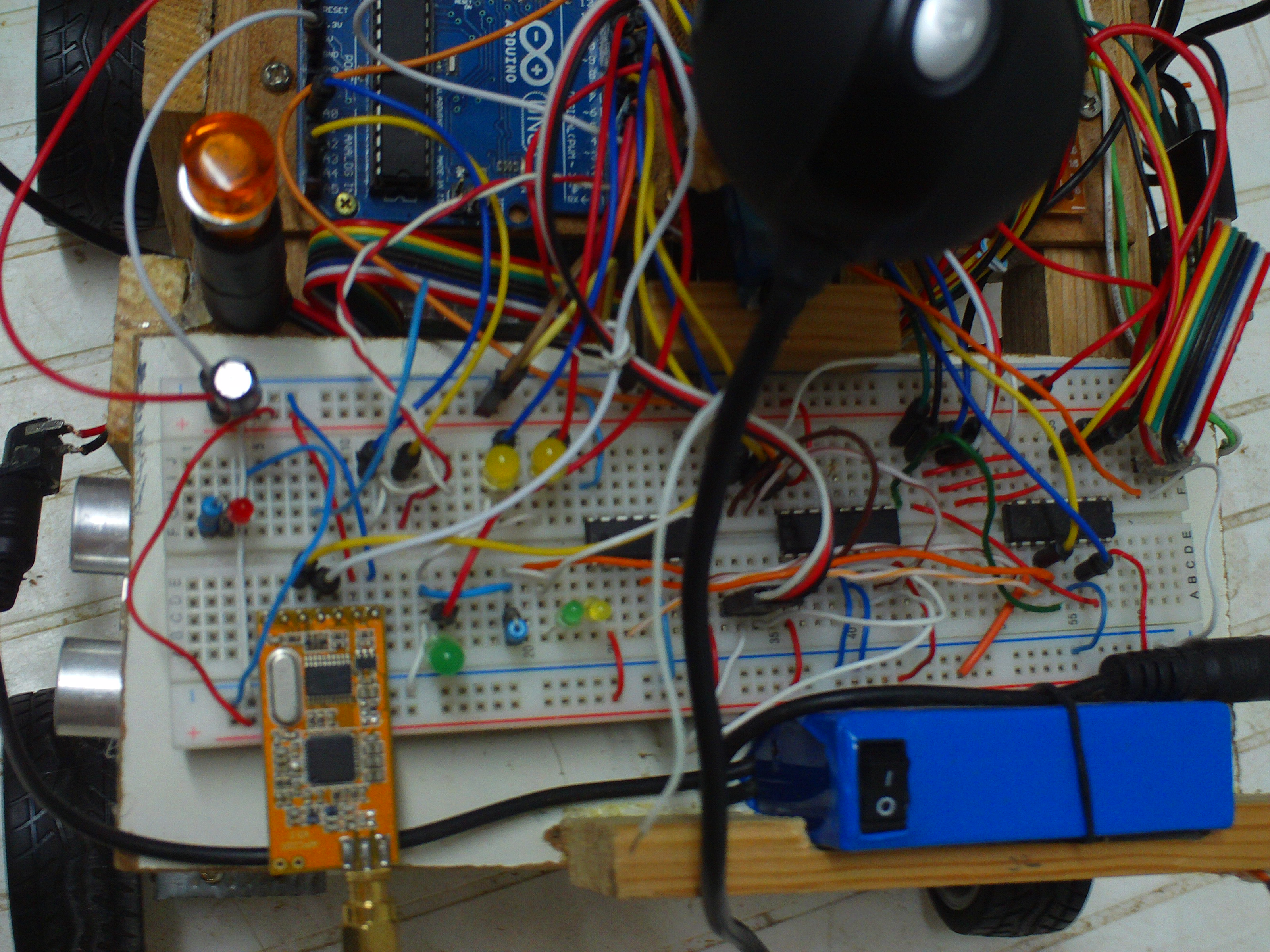
Here are some images of the robot(excuse the focus of the camera!)
The side UltraSonic sensor is used as a part of a ‘Get Around Obstacles’ algorithm. That swagger pose…regardless of the junky chassis!this front view is ridicules! this robot looks way too serious! with head on top and Sharp™ eyes on the lower deck!Those Sharp IR sensors produce too much noise on the data line, therefore, some capacitors should be added. Moreover, there is a Micro servo rotates the sensors left/right to get an idea of the surroundings while on autonomous mode.Raspberry pi, being ran as a webcam server for the moment, but a lot of plans on the way to harness its capabilities later on(since it’s a credit sized computer!)Arduino UNO board, which is the (current)brains behind this robot.this is the motor driver board; underneath this orange heatsink(that i got from an old PC) are 2 L293D ICs that control the 4 motors directions.close-up on the upper deck, that’s how the camera’s mounted, on top of a servo with a custom made holder. When shit hits the fan, this orange indicator light should burns up!!this is not some messy wirings, this is ThunderWiring!!!! The blue thing is the battery(12v dc 1800mah) and the orange board is the wireless receiver(APC220) with the antenna attached to it Those ICs, are shift registers! they’re cool too!some parts on the robot require different voltage, so that the 12v battery doesn’t fry them, i used voltage regulators, that divide the voltage of the battery, also it works way better than voltage divider circuits that use 2 resistors(a google search reveals the mystery)555 timer chip used to blink 2 indicator LEDs. Nothing fancy here.the raspberry pi set-up: on the 2 USB ports; one for the wifi dongle and the second for the webcam. Also it got an 8G SD card and a power supply input. No connection whatsoever is between the laptop and the raspberry pi!!the SD card and micro USB power supply connectedthe transmitter that used to control the robot wirelessly, it has the same APC220 module as on the robot but figured as a transmitter this time. Also here, the Arduino UNO runs the show, as it reads data from the joysticks and transmits some bytes accordingly. The LCD should display information regarding the robot performance, however i got it fried 😦some indicator LEDs. 2 potentiometers for the LCD brightness/contrast and the other for the camera tilting control. Toggle switches to flip between the different controlling modes.
Thanks for reading that far and going through the story of my 2013 summer time. It was a joy to work on something and to get it working eventually..regardless of all the bugs and errors and ‘turn downs’ through the way, that where lessons are, after all!
sorry i cannot capture a video of it running…but for now, i am storing it in a box for 3-4 years until i got more academic knowledge that should hopefully upgrade its intelligence….
its all done by the arduino, you read the signals from the distance sensors via the arduino ” analog in” pins and you program the arduino to control the robot(the motors)without a manual human interfacing…
thank you!
i know, there are factory-made chassis and they are elegant and great, however, part of the project was to build the chassis from scratch(believe me, it’s real fun and nice feeling to make it yourself than buying it!!).
Beloved Brother,
Do you have the Schematics and Arduino Code? libary for this robot of yours?
I would appreciate if you did send me the code and Schematics and arduino code, i am working on a explorer robot and i am stuck.
Peace and blessings
Hey! Thank you for tuning in!
what part exactly are you interested in(motors, LCD, wireless,..)? Is your robot wireless? what motors are you using(servo, steppers, dc,..)?
I have got lots of part, i tho about build a explorer robot with huminity and temp sensor, gas sensor, i have 6 pcs 1:10 RC wheel and rim with 6V dc motors that is 120rpm, raspberry pi. 5 pcs 2 axis PS sticks, Arduino Mega 2652, arduino Uno, W5100 ethernet shield, L293D Motor Shield, Sharp Infrared sensor, 10 pcs sonar sensor, ardu’cam. i have been fighting with the code writing for months and everything seems to take much longer time then i thoght,
So i come across this project, and it looks like the one i am trying to build, but mine has 6 pcs of motors and 6 pcs of 1:10 RC wheels. what got me more interessted in your project is the controller with the liquidcrystal LCD. so since i am stock with the coding, i tho to ask you nicely for your code, just to have some stable foundation so i can work on it to build it up more and more.
Sincerly:
Yaser Feyli
P/S I thogt about put a 6 Dof Arduino robotic arm on it, if not two arms, and i tho also mount on Xbox360 Kinect sensor, like a mars robot that sense moist, temprature, humidity, gas, range. vibration, sound sensor etc etc.
Sensors
Gas
MQ4 Methane Gas sensor
Mq7 Carbon Monoxide Gas Sensor
MQ8 Hydrogen Gas sensor
Temperature
DHT11 temperature and humidity
TMP36 temperature sensors
Don’t worry if it’s taking long time to get the code running! that’s how learning to good at programming looks like 🙂
Anyway…For the motors i used the H-bridge IC and controlled it through the UNO.
it doesn’t matter if you have 6 motors or 100! since the concept is the same.
For the GLCD(Graphic LCD) there is a library which you need to download from Arduino’s website, I did a post explaining how to use and connect the GLCD.
I used the rasperry pi for the camera only.
I had published the code here: https://github.com/ThunderWiring/wireless-arduino-robot you can have a look at it. It has a lot of sketches and such..
Beloved brother,
Do you have all the library and the schematics for the project?
How do i put all this Sketches into my Arduino Mega 2560? when i open a sketch i only can upload one. you lost me there.
the only schematic i used was for connecting the GLCD, other than this, i didn’t use any schematics..in the “readme” file in the github link i previously sent you, i explained about the code


Looks pretty cool. Mind if I ask what software you use for the autonomous mode?
LikeLike
its all done by the arduino, you read the signals from the distance sensors via the arduino ” analog in” pins and you program the arduino to control the robot(the motors)without a manual human interfacing…
LikeLike
You can have a look to improve with a better chasis:
http://www.picaxe.biz/tienda/producto/GX-730/1/chasis-robot-metalico-con-dos-motoreductores-y-portapilas
Anyway you did a great job and I like so much.
LikeLike
thank you!
i know, there are factory-made chassis and they are elegant and great, however, part of the project was to build the chassis from scratch(believe me, it’s real fun and nice feeling to make it yourself than buying it!!).
LikeLike
Beloved Brother,
Do you have the Schematics and Arduino Code? libary for this robot of yours?
I would appreciate if you did send me the code and Schematics and arduino code, i am working on a explorer robot and i am stuck.
Peace and blessings
LikeLike
Hey! Thank you for tuning in!
what part exactly are you interested in(motors, LCD, wireless,..)? Is your robot wireless? what motors are you using(servo, steppers, dc,..)?
LikeLike
I have got lots of part, i tho about build a explorer robot with huminity and temp sensor, gas sensor, i have 6 pcs 1:10 RC wheel and rim with 6V dc motors that is 120rpm, raspberry pi. 5 pcs 2 axis PS sticks, Arduino Mega 2652, arduino Uno, W5100 ethernet shield, L293D Motor Shield, Sharp Infrared sensor, 10 pcs sonar sensor, ardu’cam. i have been fighting with the code writing for months and everything seems to take much longer time then i thoght,
So i come across this project, and it looks like the one i am trying to build, but mine has 6 pcs of motors and 6 pcs of 1:10 RC wheels. what got me more interessted in your project is the controller with the liquidcrystal LCD. so since i am stock with the coding, i tho to ask you nicely for your code, just to have some stable foundation so i can work on it to build it up more and more.
Sincerly:
Yaser Feyli
LikeLike
P/S I thogt about put a 6 Dof Arduino robotic arm on it, if not two arms, and i tho also mount on Xbox360 Kinect sensor, like a mars robot that sense moist, temprature, humidity, gas, range. vibration, sound sensor etc etc.
Sensors
Gas
MQ4 Methane Gas sensor
Mq7 Carbon Monoxide Gas Sensor
MQ8 Hydrogen Gas sensor
Temperature
DHT11 temperature and humidity
TMP36 temperature sensors
Light
Generic brand light sensor
ML8511-UV Sensor
Pressure/Altitude
BMP180 pressure/altitude/Temperature sensor
LikeLike
Don’t worry if it’s taking long time to get the code running! that’s how learning to good at programming looks like 🙂
Anyway…For the motors i used the H-bridge IC and controlled it through the UNO.
it doesn’t matter if you have 6 motors or 100! since the concept is the same.
For the GLCD(Graphic LCD) there is a library which you need to download from Arduino’s website, I did a post explaining how to use and connect the GLCD.
I used the rasperry pi for the camera only.
I had published the code here: https://github.com/ThunderWiring/wireless-arduino-robot you can have a look at it. It has a lot of sketches and such..
LikeLike
Subhana’llah i see that you have the holy Qur’an on your workbench.
Peace and blessing beupon you!
LikeLike
Beloved brother,
Do you have all the library and the schematics for the project?
How do i put all this Sketches into my Arduino Mega 2560? when i open a sketch i only can upload one. you lost me there.
LikeLike
the only schematic i used was for connecting the GLCD, other than this, i didn’t use any schematics..in the “readme” file in the github link i previously sent you, i explained about the code
LikeLike